Roughly 90 minutes if this is your first time soldering, 30 if it is not.
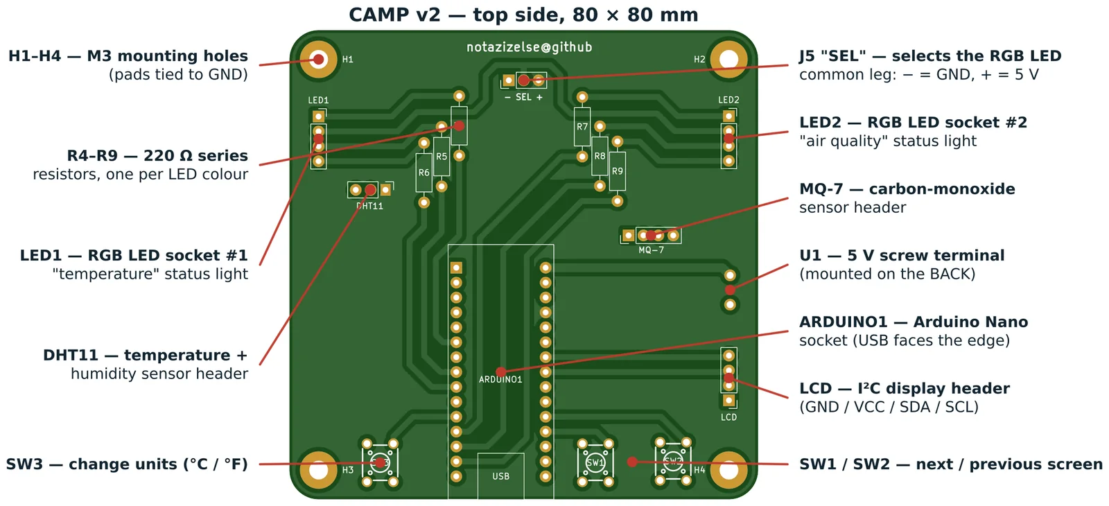
Before you start
Lay everything out and check it against this list. Missing one 220 Ω resistor at step 1 is annoying; discovering it at step 7 means desoldering.
| Position on the board | What goes there | How many |
|---|---|---|
R4 R5 R6 R7 R8 R9 |
220 Ω resistor (red–red–brown–gold) | 6 |
SW1 SW2 SW3 |
6 × 6 mm tactile button | 3 |
J5 (marked − SEL +) |
1×3 male pin header + one jumper cap | 1 |
DHT11 |
1×3 male pin header | 1 |
MQ-7 |
1×4 male pin header | 1 |
LCD |
1×4 male pin header | 1 |
LED1 LED2 |
1×4 female socket | 2 |
ARDUINO1 |
1×15 female socket | 2 |
U1 (back of the board) |
2-way 5 mm screw terminal | 1 |
H1 H2 H3 H4 |
M3 screw + standoff (optional) | 4 |
Set your iron to about 330 °C. Every joint here is a plated through-hole: heat the pad and the leg together for two seconds, feed solder into the joint (not onto the iron), count one more second, take the solder away, then the iron. A good joint looks like a small shiny volcano, not a ball.
Order of work
The rule is shortest part first. Each time you turn the board over to solder, the parts already fitted should be short enough that the board still lies flat and holds them in place. If you solder the Arduino sockets first, everything after that will sit crooked.
1 — The six resistors (R4–R9)
Bend the legs down close to the body, drop them in flat, and splay the legs slightly underneath so they do not fall out when you flip the board. Resistors have no polarity, so direction does not matter.
Solder all twelve joints, then clip the legs flush.
Why 220 Ω? Each one sits between an Arduino pin and one colour of an RGB LED. The Arduino puts out 5 V; a red LED drops about 2 V and wants ~15 mA. (5 − 2) ÷ 0.015 = 200 Ω, and 220 Ω is the nearest standard value. Without it the LED draws whatever it can and destroys itself.
2 — The three buttons (SW1, SW2, SW3)
A 4-leg tactile button only drops into the board one way — if it does not go in, rotate it 90°. Push until it clicks flat against the board. Solder all four legs of each.
The legs are in two pairs that are permanently joined inside the button; the switch connects the pairs to each other when you press it. The board only uses one leg from each pair, which is why two of the four pads on each switch are unconnected.
3 — J5, the SEL header
A 1×3 male header. Push the plastic spacer flat against the board, solder the middle pin first, check it is standing straight, then do the other two.
This is the jumper that chooses how your RGB LEDs are wired. Do not fit the jumper cap yet — that comes at step 8.
4 — The three module headers
DHT11 (3 pins), MQ-7 (4 pins) and LCD (4 pins), all male headers. Same technique:
one end pin, check square, then the rest.
Get these straight. A crooked header still works electrically but the module sits at an angle and eventually the joint cracks.
5 — The two LED sockets (LED1, LED2)
These are 1×4 female sockets, not the LEDs. The LEDs push into them afterwards, which means a student can swap a dead LED, or try a common-anode one, without a soldering iron.
6 — The Arduino socket (ARDUINO1)
Two 1×15 female sockets, and the fiddliest step on the board.
- Push both sockets into the board but do not solder yet.
- Plug the Arduino Nano into both sockets. This forces them exactly parallel and exactly the right distance apart.
- Turn the whole assembly over, resting on the Nano, and solder one pin at each far corner — four joints total.
- Turn it back, check the sockets sit flat against the board with no gap.
- Now solder the remaining 26 joints.
- Pull the Nano out.
Note the USB outline printed on the silkscreen at the bottom edge — that is which way
round the Nano goes.
7 — The screw terminal (U1) — on the back
This one goes on the other side of the board. Look at the back: you will find the U1
outline with + and − markings next to it, near the university logo.
Fit it with the wire openings facing outwards, off the edge of the board, so you can get a screwdriver and a wire into it once everything else is assembled.
8 — Set the LED jumper
Look at the silkscreen next to J5: − SEL +.
- Common-cathode RGB LEDs (the usual kind): put the jumper cap on the
−side, over pins 1 and 2. In the sketch,COMMON_ANODE = false. - Common-anode RGB LEDs: jumper on the
+side, pins 2 and 3, andCOMMON_ANODE = true.
If you are not sure which kind you have, start with common-cathode. If the LEDs come on when they should be off and the colours look inverted, you have the other kind — move the jumper and flip the setting.
Fitting the LEDs
A 4-pin RGB LED has one leg longer than the other three. That long leg is the common one,
and it goes into position 2 of the socket — the second hole counting from the top of
the board (LED1 and LED2 are both oriented the same way, pin 1 at the top).
The other three legs are red, green and blue in the order the LED's datasheet gives. If a colour comes out wrong, pull the LED, rotate it, and try again — nothing is damaged by getting this wrong, since every leg has its own resistor.
Plugging in the modules
| Header | Module | Watch out for |
|---|---|---|
DHT11 |
temperature / humidity | 3 pins: VCC, DATA, GND, top to bottom. Backwards will not damage it but reads nan. |
MQ-7 |
carbon monoxide | 4 pins. Pin 1 is the analogue output, pin 2 the digital one, then GND, then VCC. Check the labels printed on your module — suppliers order these differently. |
LCD |
I²C display backpack | 4 pins: GND, VCC, SDA, SCL, top to bottom. |
The MQ-7 gets noticeably warm in normal operation. That is its internal heater, not a fault.
First power-up
Do this before flashing anything.
- Nano out of its socket. Modules unplugged.
- Power the board — USB into the Nano is easiest, so put the Nano in for this. Or 5 V into
the screw terminal,
+and−as marked. - Measure with a multimeter between the
+5VandGNDpins of any module header. You should read 4.8 – 5.2 V. - If you read 0 V, or the Nano gets hot, or your USB port complains — disconnect immediately and look for a solder bridge, especially across the Arduino socket pins, which are the closest together on the board.
⚠️ Never connect USB and the screw terminal at the same time. This board has no protection between them.
Once 5 V is confirmed, go to flashing the firmware.
Checking your work
Hold the board up to a light and look across the back at a shallow angle. You are looking for:
- Dull, grey, or crazed-looking joints — reheat them, they are cold joints.
- Solder blobs bridging two adjacent pads — most likely between the Arduino socket pins. Add flux, run a clean iron tip between them, or use braid.
- Legs not clipped — a stray resistor leg touching a neighbouring pad is the classic intermittent fault.
- Rings of bare board around a pad with a thin joint — not enough solder; add more.
If something does not work, troubleshooting.md covers the usual
causes.