A CubeSat payload computer you can build in a weekend.
An 80 × 80 mm Arduino Nano carrier board that turns a handful of loose sensor modules into one tidy instrument: it reads the temperature, the humidity and the carbon-monoxide level of the air around it, shows them on a small screen, and reports them over USB — the same job the payload computer of a real CubeSat does.
Every part is through-hole, so it can be assembled with a soldering iron and no magnifying glass. The board carries no chips of its own — the Arduino Nano does all the thinking. What the board gives you is clean wiring, the right resistors in the right places, and connectors that only fit one way.
🇺🇿 Bu hujjatning o'zbekcha versiyasi: README.uz.md 🔧 Designing a rev C, or want the netlist and fab notes? → docs/hardware-reference.md
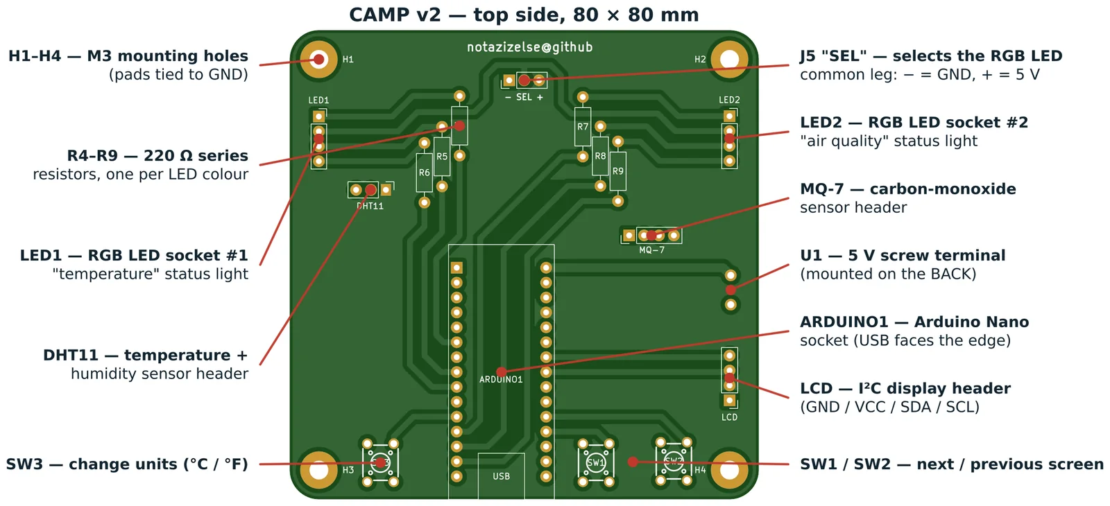
Table of contents
- What you need
- How the board works
- The schematic
- Build it
- Flash it
- Use it
- Things to try
- When it does not work
- Repository layout
- Opening the project in KiCad
- Getting the board made
- Credits
What you need
Parts that go on the board
| Ref | Qty | Part | Notes |
|---|---|---|---|
| ARDUINO1 | 1 | Arduino Nano (ATmega328P) | Use two 1×15 female headers so the Nano can be unplugged |
| R4 – R9 | 6 | 220 Ω resistor, ¼ W | Colour bands: red–red–brown–gold |
| LED1, LED2 | 2 | 4-pin RGB LED, 5 mm | Fitted in 1×4 sockets, so they can be swapped |
| SW1, SW2, SW3 | 3 | 6 × 6 mm tactile push button | 4-leg, 5 mm tall |
| J5 "SEL" | 1 | 1×3 pin header + jumper cap | Chooses common-cathode or common-anode LEDs |
| DHT11 | 1 | 1×3 pin header | For the temperature / humidity module |
| MQ-7 | 1 | 1×4 pin header | For the carbon-monoxide module |
| LCD | 1 | 1×4 pin header | For the I²C display module |
| U1 | 1 | 2-way 5 mm screw terminal | Mounted on the back of the board |
| H1 – H4 | 4 | M3 screw + standoff | Optional, for mounting into a frame |
The full machine-readable list, with LCSC order codes, is in
campv2/production/bom.csv.
Modules that plug into the board
- DHT11 temperature + humidity module (3-pin version)
- MQ-7 carbon-monoxide module (4-pin version, with both analogue and digital outputs)
- 16 × 2 LCD with an I²C backpack (a small board soldered to the back of the display with only 4 pins: GND, VCC, SDA, SCL)
- 2 × common-cathode RGB LEDs, 4 legs each
Tools
Soldering iron, solder, side cutters, a small screwdriver for the terminal, and a computer with the Arduino IDE.
How the board works
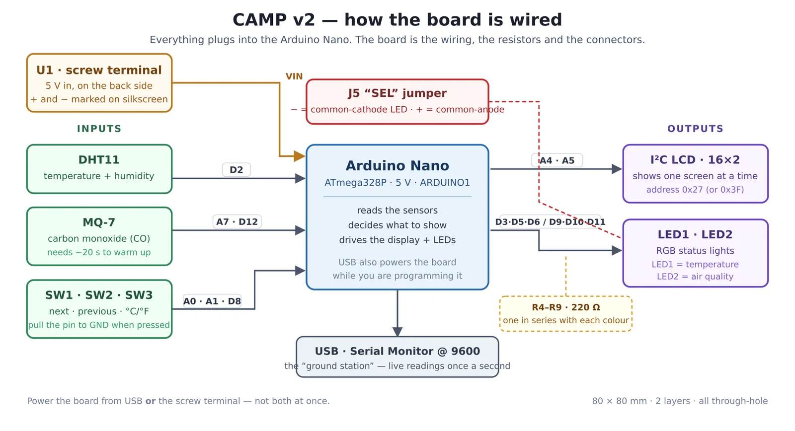
Read it left to right. The three things on the left tell the Arduino something. The two things on the right are how the Arduino tells you something. Nothing on this board talks to anything else directly — every signal goes through the Nano.
The pin map
This is the single most important table in the repository. It is what the board is.
| Arduino pin | Goes to | What it does |
|---|---|---|
D2 |
DHT11 pin 2 | Temperature and humidity data (one wire, both values) |
A7 |
MQ-7 pin 1 | CO level, as a voltage — analogue in only, cannot be a digital pin |
D12 |
MQ-7 pin 2 | The MQ-7 module's own alarm output |
A0 |
SW1 | "Next screen" button |
A1 |
SW2 | "Previous screen" button |
D8 |
SW3 | "Change units" button (°C ↔ °F) |
A4 |
LCD pin 3 | I²C SDA — data |
A5 |
LCD pin 4 | I²C SCL — clock |
D3 D5 D6 |
LED1 via R4, R5, R6 | Red, green, blue of the first RGB LED |
D9 D10 D11 |
LED2 via R7, R8, R9 | Red, green, blue of the second RGB LED |
VIN |
U1 pin 1 | 5 V from the screw terminal |
GND |
U1 pin 2, every module, H1–H4 | Ground |
All six LED pins are PWM-capable, which is why the LEDs can fade smoothly between colours instead of only switching on and off.
Three details worth understanding
The buttons have no resistors. Each button connects its Arduino pin to GND, and
nothing else. The pull-up resistor that holds the pin HIGH lives inside the ATmega328P
and is switched on in software with pinMode(pin, INPUT_PULLUP). So a button reads
HIGH when it is not pressed and LOW when it is — backwards from what you might
expect, and a classic thing to get stuck on.
J5 decides which way the LEDs are wired. A 4-pin RGB LED has three separate colour
legs and one leg they all share. On a common-cathode LED that shared leg must go to
GND; on a common-anode LED it must go to +5 V. Rather than pick one and lock you in,
this board brings the shared leg out to the middle pin of J5, marked SEL on the
silkscreen, with − (GND) on one side and + (5 V) on the other. Put the jumper cap on
the side your LEDs need, and set COMMON_ANODE in the sketch to match.
Each LED colour gets its own 220 Ω resistor. An LED will happily draw enough current to destroy itself, and the three colours inside an RGB package have different forward voltages, so one shared resistor would make the colours uneven. Six resistors, one per colour channel: R4/R5/R6 for LED1, R7/R8/R9 for LED2.
The schematic
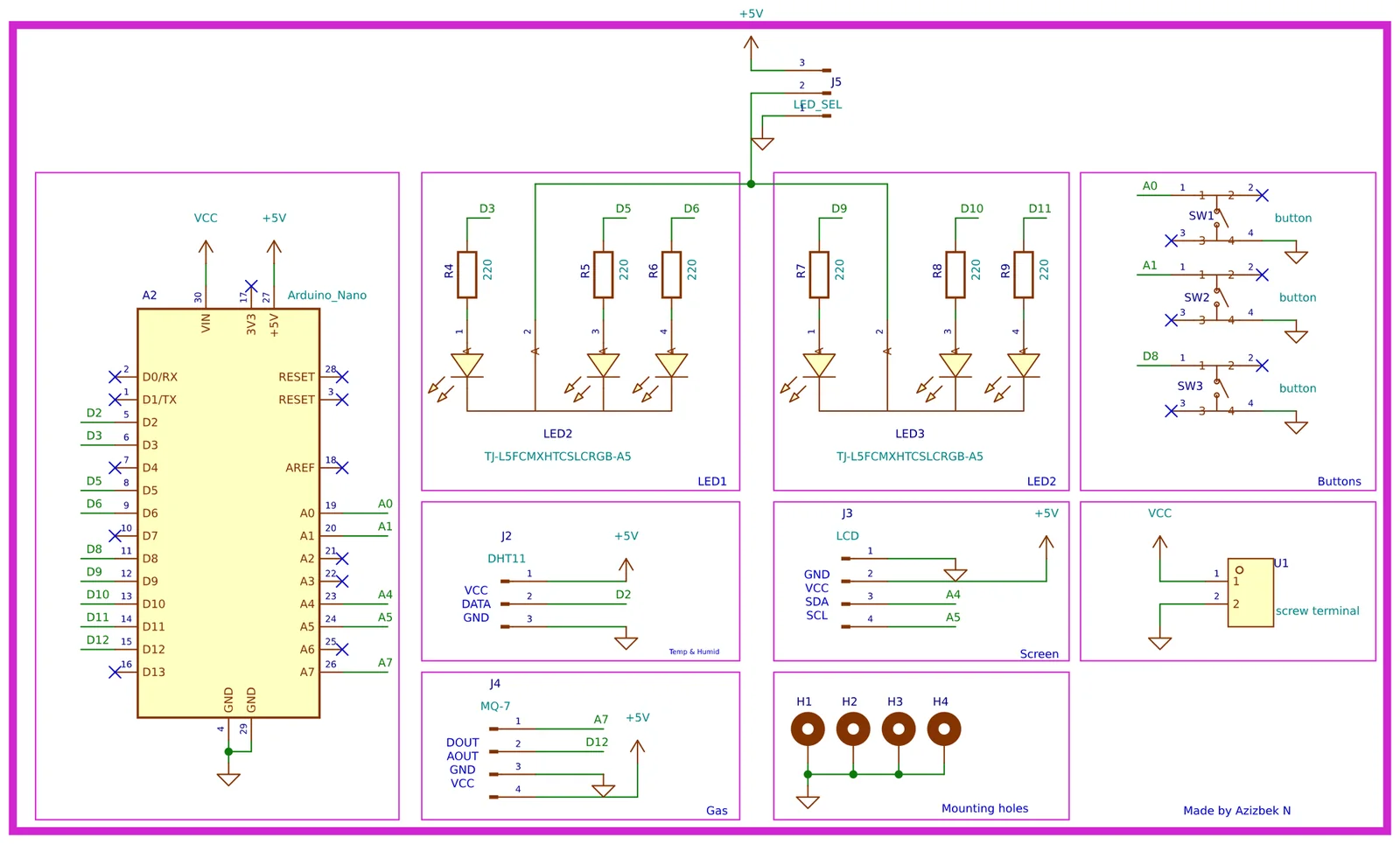
Higher-resolution vector version: docs/images/schematic.svg.
The KiCad source is campv2/campv2.kicad_sch.

The drawing is deliberately split into labelled boxes — Buttons, Temp & Humid,
Gas, Screen, Mounting holes, and the two LED blocks — so you can read one idea at a
time. Instead of drawing a wire all the way from the Nano to each block, the schematic
uses net labels: two wire ends carrying the same label, like A4, are the same
electrical node even though no line connects them on paper. This is how real schematics
stay readable.
Build it
Full step-by-step version with photos of each stage: docs/assembly.md.
The short version:
Solder from shortest part to tallest, so that each time you flip the board over, the parts you have already fitted hold themselves flat against it.
- R4 – R9, the six 220 Ω resistors. They lie flat. Direction does not matter.
- SW1, SW2, SW3, the tactile buttons. They only drop in one way round.
- J5, the 3-pin
SELheader. - DHT11 / MQ-7 / LCD headers (3, 4 and 4 pins).
- LED1, LED2 sockets — 1×4 female headers, not the LEDs themselves.
- ARDUINO1 — two 1×15 female headers. Fit the Nano into them before soldering so they end up parallel, then solder one pin at each end, check it is square, and finish.
- U1, the screw terminal — on the back of the board, wire openings facing out.
Then plug in the modules, put a jumper cap on J5, and drop the Nano into its socket with the USB connector facing the edge of the board (the silkscreen shows you where).
⚠️ Power the board from USB or the screw terminal — never both at once. The screw terminal feeds the Nano's
VINpin. Feeding 5 V intoVINwhile USB is also connected puts the Nano's regulator and your USB port in a fight neither wins.
Flash it
The sketch is campv2/firmware/CubeSat/CubeSat.ino.
- Install the Arduino IDE.
- Install three libraries via Tools → Manage Libraries…
-
LiquidCrystal I2Cby Frank de Brabander -DHT sensor libraryby Adafruit -Adafruit Unified Sensorby Adafruit (No internet in the classroom? Known-good copies are vendored inArduino/libraries/— see the README there.) - Tools → Board → Arduino Nano, Tools → Processor → ATmega328P.
If uploading fails with a
avrdude: stk500_recv()error, switch the processor to ATmega328P (Old Bootloader). Most cheap Nano clones need this. - Open
CubeSat.ino, put your own name inSTUDENT_NAME, and press Upload.
Settings you are meant to change
They are all together at the top of the sketch, in the block marked
PART 1 — SETTINGS YOU ARE MEANT TO CHANGE:
| Setting | What it is for |
|---|---|
STUDENT_NAME |
Shown on the LCD at start-up |
LCD_ADDRESS |
0x27 for most I²C backpacks; try 0x3F if the screen stays blank |
COMMON_ANODE |
false for common-cathode LEDs (J5 on −), true for common-anode (J5 on +) |
TEMP_COLD_C, TEMP_HOT_C |
When LED1 turns blue and when it turns red |
CO_WARNING_PPM, CO_DANGER_PPM |
When LED2 turns amber and when it turns red |
CALIBRATE_MODE, MQ7_R0 |
MQ-7 calibration — see below |
Everything below that block is the wiring, and changing it will simply stop the board from matching the copper.
Use it
The LCD shows one screen at a time. SW1 walks forward through them, SW2 walks back, and they wrap around:
   NAME  →  TEMPERATURE  →  HUMIDITY  →  CARBON MONOXIDE
     ↑                                          │
     └──────────────────────────────────────────┘
SW3 switches the temperature between °C and °F.
The two RGB LEDs are status lights, exactly like the ones on a real satellite:
| LED1 — temperature | LED2 — air quality | |
|---|---|---|
| 🔵 blue | below 18 °C | — |
| 🟢 green | comfortable | CO below 35 ppm |
| 🟡 amber | — | CO 35 – 200 ppm |
| 🔴 red | above 28 °C | CO above 200 ppm |
Open the Serial Monitor at 9600 baud and the board reports every reading once a second. That is your ground station.
Calibrating the MQ-7
An MQ-7 does not measure CO directly — it measures its own resistance, which changes when
CO touches it. To turn that into a number in ppm the sketch needs R0, the sensor's
resistance in clean air, and every sensor's R0 is different.
- Set
CALIBRATE_MODE = trueand upload. - Leave the board in fresh air, powered, for a few minutes.
- Read the number printed in the Serial Monitor, copy it into
MQ7_R0. - Set
CALIBRATE_MODE = falseand upload again.
Until you do this, treat the ppm figure as "roughly" rather than "actually". Also give the
sensor about 20 seconds after power-on before believing anything — its heater has to come
up to temperature first, and the screen says warming up while it does.
Things to try
The board was designed to be poked at. Some starting points, roughly in order of difficulty:
- Change the temperature thresholds so the LED turns red when you breathe on the sensor.
- Add a fifth screen showing how long the board has been running.
- Make LED2 pulse instead of sitting at a steady colour when CO is in the warning band.
- Log the serial output to a file and plot a day of temperature readings.
- Use the MQ-7's digital alarm pin (
D12) to flash both LEDs at once. - Replace the DHT11 with a DHT22 — same 3 pins, better accuracy. What changes in the code?
- Sketch a rev C: what would you add if you had two more pins?
When it does not work
The full list is in docs/troubleshooting.md. The four that
catch nearly everybody:
| Symptom | Almost always |
|---|---|
| LCD backlight is on but shows nothing, or white squares | Wrong I²C address — change LCD_ADDRESS from 0x27 to 0x3F |
Upload fails, stk500_recv(): programmer is not responding |
Wrong bootloader — Tools → Processor → ATmega328P (Old Bootloader) |
| LEDs are on when they should be off, colours inverted | J5 jumper and COMMON_ANODE disagree — flip one of them |
Temperature reads nan or the screen says the sensor failed |
DHT11 in backwards, or its middle pin not seated |
Repository layout
camp/
├── README.md                    ← you are here (English)
├── README.uz.md                 ← same thing, in Uzbek
├── CHANGELOG.md                 ← what changed between board revisions
│
├── campv2/                      ← THE BOARD, and everything that belongs to it
│   ├── campv2.kicad_pro         ·  open this one in KiCad
│   ├── campv2.kicad_sch         ·  schematic
│   ├── campv2.kicad_pcb         ·  layout
│   ├── fp-lib-table             ·  points at ../lib (project-relative)
│   ├── sym-lib-table
│   │
│   ├── firmware/
│   │   └── CubeSat/CubeSat.ino  ← THE CODE. Open this in the Arduino IDE
│   │
│   └── production/              ← WHAT THE FACTORY GETS. Do not edit by hand
│       ├── …PCB_B.zip           ·  upload this file to JLCPCB / PCBWay as-is
│       ├── bom.csv              ·  parts list with LCSC codes
│       ├── positions.csv        ·  pick-and-place positions
│       ├── designators.csv
│       └── netlist.ipc          ·  for the fab's electrical test
│
├── lib/                         ← shared KiCad libraries
│   ├── lcsc/                    ·  symbols + footprints pulled from LCSC
│   └── 3d/                      ·  STEP models for the 3D viewer
│
├── production/                  ← artwork and reference plots. NOT the fab
│   ├── turin_logo2.kicad_mod    ·  package — that is in campv2/production/
│   ├── assotsiatsiya_logo…      ·  the two logos printed on the back
│   ├── logo*.kicad_mod          ·  earlier versions of them
│   ├── campv2-*.pdf             ·  copper and outline plots, for checking
│   └── 3d.step                  ·  the assembled board, for mechanical fit
│
├── Arduino/libraries/           ← offline copies of the three Arduino libraries
│
├── docs/
│   ├── hardware-reference.md    ← for engineers: nets, design rules, how to modify
│   ├── assembly.md              ← for students: build it step by step
│   ├── troubleshooting.md
│   └── images/                  ← every picture used in these documents
│
├── lcsc.py, lcsc.txt            ← pulls a KiCad part from an LCSC order code
│
└── archive/                     ← OLD WORK. Nothing here is used by the current board
    ├── camp/                    ·  rev A, superseded
    ├── camp_demo/               ·  a tiny one-LED teaching board
    └── camp_t9/                 ·  an empty project stub
The rule: everything the current board needs is inside campv2/ — schematic,
layout, sketch and fab package, one folder. lib/ is what KiCad loads behind the
scenes. docs/ is for you. Nobody needs archive/.
⚠️ Two folders are called
production, and they are not the same thing.campv2/production/is the fab package — the gerbers, BOM and pick-and-place file you send to the factory. The top-levelproduction/holds the logo footprints and reference plots. "Send them the production files" means the zip incampv2/production/.
Opening the project in KiCad
You need KiCad 10.0 or newer — the files use the 2026 file format and older KiCad will refuse to open them.
git clone https://github.com/notazizelse/camp.git
cd camp
Then open campv2/campv2.kicad_pro. That is all. There is no "configure paths"
step, no environment variables to set, and no libraries to install:
- The symbol and footprint libraries are found through
${KIPRJMOD}, KiCad's built-in "wherever this project happens to be" variable, so they resolve on any machine. - The 3D models resolve the same way.
- Everything the board actually uses lives inside this repository.
If KiCad still complains about a missing library, that is a bug in this repository — please open an issue rather than fixing it locally, so the next person does not hit it.
Getting the board made
Upload campv2/production/TechnoCamp_Circuitry_Class_PCB_B.zip to any PCB house
without unzipping it, and take the defaults:
| Setting | Value |
|---|---|
| Size | 80 × 80 mm |
| Layers | 2 |
| Thickness | 1.6 mm |
| Min track / clearance | 0.5 mm / 0.5 mm |
| Min hole | 0.3 mm |
| Vias | none — every connection is a track or a pad |
| Surface finish | HASL is fine |
The design rules are deliberately loose — nothing on this board is near any fab's limits, which is what makes it cheap and reliable to produce in class quantities.
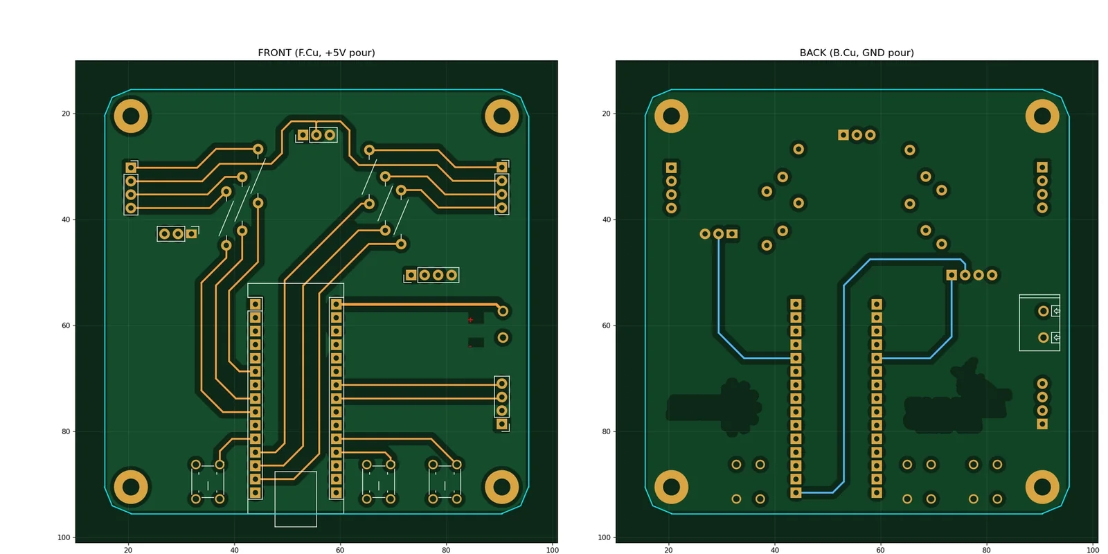
The board has a +5 V pour on the front and a GND pour on the back. That gives every part a low-impedance path to both rails without routing a single power track, and it is why the back of the board looks almost empty.

Across the top of the back, above the mounting holes, the board carries PER ASPERA AD ASTRA — through hardships, to the stars.
Credits
Designed by Azizbek N for TechnoCamp 2026, run by the Robotics and Engineering Association at Turin Polytechnic University in Tashkent. Both logos are printed on the back of the board.
The Arduino Nano pinout reference embedded in the schematic is from Last Minute Engineers and is used for reference only.
Licence: not yet chosen. Until one is added, treat this as "ask before reusing". For a teaching board like this, the usual pairing is CERN-OHL-P v2 for the hardware and MIT for the firmware.